GPS disciplined Oscillator 1x10Mhz or 4x10MHz
- THE IDEA
The Idea was to build a very accurate Reference Oscillator at much lower cost then a 10MHz Fequency Normal with OCXO.
Another advantage is that it needs much less time to stabilize, appr. 5mins instead of 20-30mins.
And it draws much less current.
- Features
1 or 4 x 10MHz Out
All Outputs Pure Sine Wave
Level 1 Output Version 1,5Vpp
Level 4 Output Version 2,5Vpp each
Supply +8V to +13V
Current 150mA max.
Size 4 Output Version 110x85x50mm incl. connectors
Size 1 Output Version 110x85x30mm (Slim Version) incl. connectors
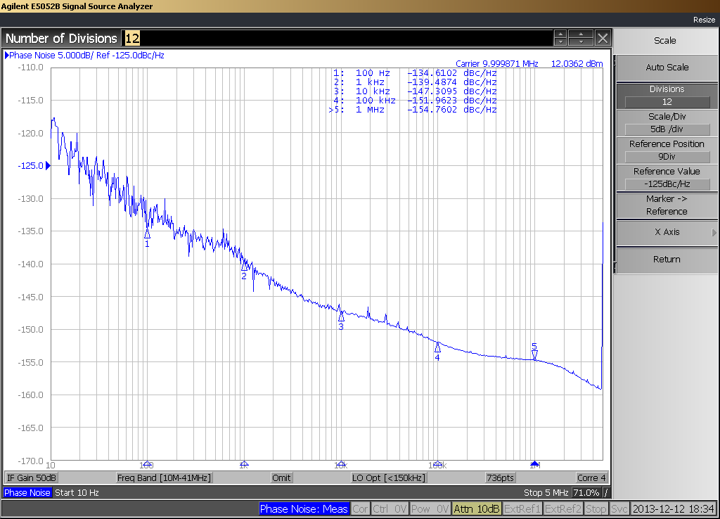
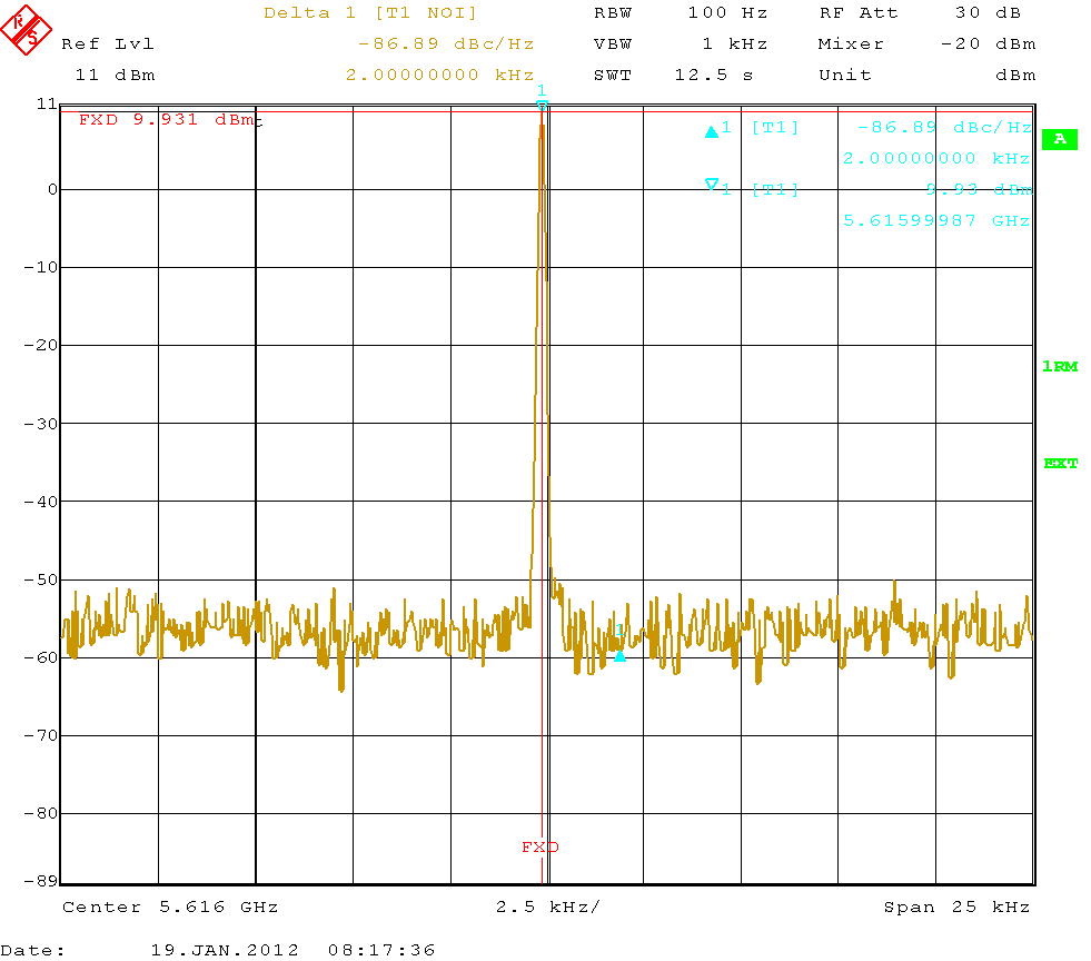
Phase Noise see Plot at the side column
- 1) GPS RX LEA5A/S UBLOX.
By default the GPS RX delivers a so called 1pps, 1 pulse per second.
By configuration this 1pps is then changed to a 800Hz square wave signal with 20% duty cycle.
For improved stability navigation mode is set to stationary.
Cable delay is adjusted to 250nS, was best result with 5m cable at active antenna.
- 2) 10MHz VCTCXO
The VCTCXO alone has a temperature stability of +/- 0,5ppm.
Ouput leevel is HCMOS A smaller value is decoupled for the PLL.
The rest is either the Output for the 1x10Mhz Version with LPF,
or the input for the Buffer Board with 4 Outputs
- 3) 800Hz PLL
The 10MHz of VCTCXO is divided down to 800Hz by 3 x 74HC390 This divided signal and the 800Hz out of the GPS RX goes to a phase comparator CD4046. It delivers a control voltage from 0V to +5V which is connected to the Vtune Port of the VCTCXO and it always tries to keep the both signals at same Phase and Frequency. The Loopfilter in the control voltage line is made as fast as possible,but slow enough to filter out the low frequency spurious from the PLL IC.
- 4) Lock Detect Indication
The PLL IC CD4046 also has a Lock Indication Pin. When both signals are the same, the voltage at this Pin goes from Low to High, in reality it is an impulse, which is very short when in lock, but still there. This is a little problem for the LED, because either it is always light on, or it is out little to early. So please give the Oscillators 1 to 2mins more after the LED is Out
- 5) FAN OUT Buffer with 4 Outputs
It provides 4 Outputs with 2Vss at 50 Ohms.
Each Output has a Low Pass Filter to get clean sine wave.
SPA, Counter, PLLs can be direct connected to the Outputs.
- 6) UART to RS232 Interface
The GPS RX has an UART interface for the configuration settings.
To convert this to RS232 (3 wire at SUB-D seriell) a MAX202 is used.
Connect a Sub-D9 female according the picture below.
- 7) PLLs integrated in the GPSDO
Generally every PLL can be integrated into a GPSDO.
In the standard version hight 50mm, 2 PLLs are possible,
e.g.25MHz and 40MHz
In the slim version hight 30mm only 1 PLL is possible.
- Click on the Photos to enlarge and close with Back Buttom !

